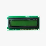
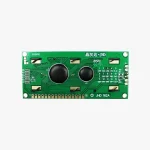
16×2 LCD Display (Green Backlight)
- Operating Voltage: 4.7V to 5.3V
- Operating Current: 1mA (without backlight)
- Can display (16×2) 32 Alphanumeric Characters
- Supports Custom Characters
- Operates in both 8-bit and 4-bit Mode
- Delivery & Return
Delivery
Store delivery FREE
1-3 working days
Home or collection point from £35.00 FREE
On all your orders for home or collection point delivery
Returns
Return
We will accept exchanges and returns of unworn and unwashed garments within 30 days of the date of purchase (14 days during the sales period).
Returns in store FREE
Your return will usually be processed within a week to a week and a half. We’ll send you a Return Notification email to notify you once the return has been completed. Please allow 1-3 business days for refunds to be received to the original form of payment once the return has been processed.
- Ask a Question
₹168
16×2 LCD Display
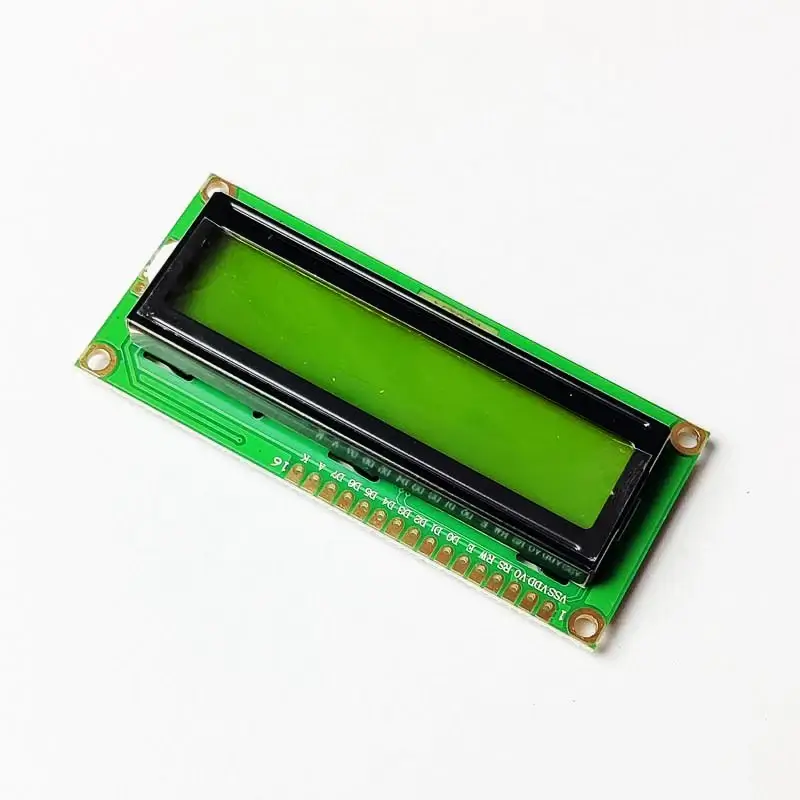
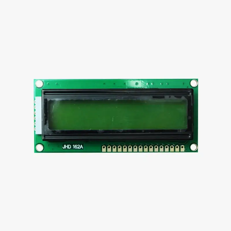
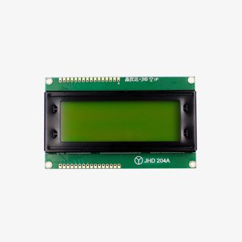
The 16×2 lcd display green backlight arduino is widely favored by both hobbyists and professionals due to its cost-effectiveness and simplicity of use. As the name implies, the 16×2 Alphanumeric LCD can display 16 Columns and 2 Rows, which amounts to a total of 32 characters. Each character can be a letter, a number, or even a custom character. This specific LCD has a green backlight, but there’s also a Blue Backlight LCD available that can make your projects more visually appealing. Regardless of the backlight color, both LCDs have the same specifications and can share the same circuit and code. If your projects require more characters to be displayed, you can consider the 20×4 Graphical LCD, which has 20 Columns and 4 Rows, and can display up to 80 characters.
Specifications :
- Operating Voltage: 4.7V to 5.3V
- Operating Current: 1mA (without backlight)
- Can display (16×2) 32 Alphanumeric Characters
- Supports Custom Characters
- Operates in both 8-bit and 4-bit Mode
LCD Module Control Pins and Power Configuration:
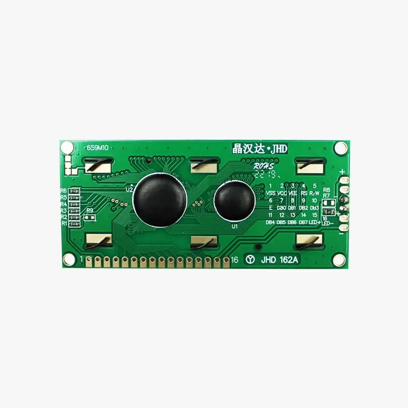
The 16×2 LCD pinout diagram is also provided. As you can see, the module has two power pins, Vss and Vcc, to power the LCD. Typically, Vss should be connected to ground and Vcc to 5V, but the LCD can also operate from voltage between 4.7V to 5.3V. Next, we have the control pins namely Contrast (VEE), Register Select (RS), Read/Write (R/W), and Enable (E). The Contrast pin is used to set the contrast (visibility) of the characters, normally it is connected to a 10k potentiometer so that the contrast can be adjusted. The Read/Write pin is usually grounded because we will only be writing characters to the LCD and not reading anything from it. The Register Select (RS) and Enable pin (E) are the control pins of the LCD and will be connected to the digital pins GPIO pins of the microcontroller. These pins are used to instruct the LCD where to place a character, when to clear it, etc.

From DB0 to DB7, we have our eight Data Pins which are used to send information about the characters that have to be displayed on the LCD. The LCD can operate in two different modes, in the 4-bit Mode only pins DB4 to DB7 will be used and the pins DB0 to DB3 will be left idle. In 8-bit Mode, all the eight-pin DB0 to DB7 will be used. Most commonly the 4-bit mode is preferred since it uses only 4 Data pins and thus reduces complexity and GPIO pin requirement on the microcontroller. Finally, we have the LED+ and LED- pins which are used to power the backlight LED inside our Display module. Normally the LED+ pin is connected to 5V power through a 100 ohm current limiting resistor and the LED- pin is connected to Ground.
PIN DESCRIPTION OF 16X2 LCD DISPLAY:
| Pin No. | Pin Symbol | Pin Name | Connection Description |
| 1 | VSS | Ground | Connected to Ground |
| 2 | VCC | Power | Connected to Power (Typically 5V) |
| 3 | VEE | Contrast | Connected to potentiometer 10k to control contrast |
| 4 | RS | Register Select | Connected to Microcontroller |
| 5 | R/W | Read/Write | Connected to Ground |
| 6 | E | Enable | Connected to Microcontroller |
| 7 | DB0 | Data Pin 0 | Connected to Microcontroller based on 4-bit or 8-bit Working Mode |
| 8 | DB1 | Data Pin 1 | |
| 9 | DB2 | Data Pin 2 | |
| 10 | DB3 | Data Pin 3 | |
| 11 | DB4 | Data Pin 4 | |
| 12 | DB5 | Data Pin 5 | |
| 13 | DB6 | Data Pin 6 | |
| 14 | DB7 | Data Pin 7 | |
| 15 | LED+ | LED Positive | Connected to 5V through 100 ohm Resistor |
| 16 | LED- | LED Negative | Connected to Ground |
| 5 |
|
0 |
| 4 |
|
0 |
| 3 |
|
0 |
| 2 |
|
0 |
| 1 |
|
0 |
- 5mm LED
- 18650 Lithium Battery
- arduino
- arduino ide
- arduino uno
- Batteries
- Battery
- Battery Accessories
- Battery Charging
- bo motor
- Capacitor
- Capacitors
- development board
- diode emitting light
- drone
- drone propellers
- drone spare parts
- LED
- LEDs
- Li-ion Battery
- light emitting diode
- li on li po
- li po and li ion
- li polymer
- lithium battery
- lithium ion
- lithium ion battery life
- Module
- NMC Cells (18540)
- non- Rechargeable Battery
- original
- Passives/Capacitors
- Passives/Diodes
- Passives/Resistors
- power
- quadcoptor
- rc drone
- Rechargeable
- Rechargeable Battery
- Resistor
- RGB
- robo
- sensor
- type of leds
- types of led lights
You may also like…
Related Products…
- Evenly lighted segments
- Common Anode Circuitry
- Color : Red
95 in stock
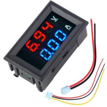
Specifications and Features of Volt meter and AMP meter:
- Voltage measuring range: DC 0-100V,
- Current measuring range: DC 0-10A
- Working voltage 4.5 to 30V DC.
- Input current: Less than 20mA
- Dual 4 bit 0.28″ clear LED display – RED for Voltage and Sky Blue for Current Display
- Display Resolution: 0.1V, 0.01A
83 in stock



Reviews
There are no reviews yet.